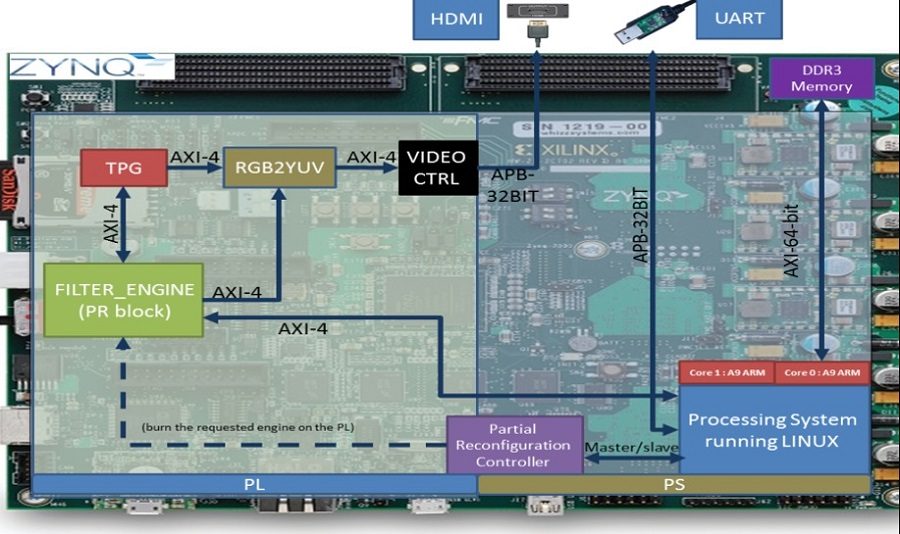
Using Xilinx partial reconfiguration technology, we implemented an ability to change the hardware system dynamically due to the application request. The hardware change is done at runtime by application & OS and the custom hardware can be supplied by the application user.

Few components are necessary for the POC:
1. TPG – Test Pattern Generator – this hardware module generated image pattern by the request of the user. The pattern can be stealth or video. The generated patterns are pushed to the custom filter (as will be described next) using DMA.
2. Partial Reconfiguration Controller – Partial Reconfiguration is the ability to dynamically modify blocks of logic by downloading partial bit files while the remaining logic continues to operate without interruption. Xilinx Partial Reconfiguration technology allows designers to change functionality on the fly, eliminating the need to fully reconfigure and re-establish links, dramatically enhancing the flexibility that FPGAs offer. The use of Partial Reconfiguration can allow designers to move to fewer or smaller devices, reduce power, and improve system upgradability. Make more efficient use of the silicon by only loading in functionality that is needed at any point in time.
3. Filter Engine – is actually a “custom hardware interface” we design in order to enable the PR functionality for the filters we implemented (2 different filters can’t be available in the system at the same time). This module can contain each one of the image filters at a single point of time. Filter engine interface will define the PR block lately. i.e. if a new created filter is requested to be burn in the specific board, it must implement the “filter engine interface”.
4. AXI 4 – The AXI Interconnect IP connects one or more AXI memory-mapped Master devices to one or more memory-mapped Slave devices. In our project we use AXI4 to connect the filter engine to the HDMI device, and the TPG to the filter engine.
5. RGB2YUV – this module converts an RGB formatted image to a YUV formatted image. We need this module because our filter engines (filters) are designed to receive RGB formatted image.
6. Video Controller – this module is the display controller of the system. It gets images from the TPG / FILTER ENGINE and displays them in the HDMI screen.

